Collection of Feather Huzzah ESP8266 workshop materials to build a plant monitor in the module CASA0014.
Goal was to build a sensor system that would monitor soil moisture and environment conditions, present live data via a webserver and send data via wifi to an MQTT server so that historic data could be stored in a data base.
Component parts of the system were built individually and then incrementally integrated into one system. Hence in the code folder there are several scripts named to describe the function they are testing. For example testEnvWeb is a demo script to test the presentation of live DHT22 sensor data via a webpage served from the Arduino Feather Huzzah.

Started by sketching out circuit design needed as per the notes highlighted in the workshop materials. The sketch below shows the outline design for v2 of the circuit:
At the top right is the circuit for the DHT22 environmental sensor. Outlined in orange is the circuit for the soil moisture sensor - note the dotted line area is the voltage divider required since the ADC pin on the Huzzah measures in a range of 0-1V (where as the board supplies 3.2V through the digital pins).
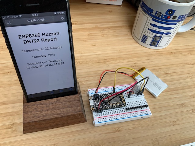
For this project three stages of prototyping were implemented. First a fully working version on breadboard which allowed me to test things like switching the voltage supply of the moisture sensor off, checking voltage divider was working how I expected, checking the range of the moisture sensor readings (note this image shows me using an LDR as an input device to test the range). Most of the testing and thinking about the circuit was done at this version of the prototype.
Next, I soldered the components together directly since the circuit was reasonably simple. At this stage I was curious to see how small I could make the package. Whilst it looked quite cool (I was inspired by sculptural Arduino project such as A Blooming Time) it ended up being a little fragile and had the potential to short easily.
As a final prototype I wanted something a little more robust that would allow a class of 25 students to make exactly the same prototype whilst also learning how to solder. The final prototype show below is a 2 layer PCB designed in Eagle. In 2020-22 the v1 design incorporated an NPN transistor so that we could use a digital switch to "turn off" the voltage supply to the soil sensor when not in use. For v2 I have removed the NPN to keep the circuit simpler since the supply to the moisture sensor can be controlled directly via the Arduino pin.
The PCB was designed using Autodesk Eagle following a workshop tutorial that will be introduced later in T1 in CASA0016 - Make Design Build. The schematic used is shown below:
This schematic was used to generate the following board layout:
An additional step was included to add the CASA logo to the silkscreen - this required the conversion of the vector CASA logo into a BMP (I used an online conversion tool - had to fiddle with image sizes to get what worked ok since found it hard to scale while in Eagle). Then I followed the example on Sparkfun to import the .bmp file using the command:
run import-bmp
Note: make sure to select import to layer 21 (tPlace) if you want the logo to appear on the silkscreen (or bPlace if you want it on the back!). I found this Autodesk description of layers useful for understanding what happens on which layers in Eagle - note to self: remember to select which layer you are trying to manipulate when moving stuff around on the PCB!
Reminders for next time.
- Martins Eagle workshop materials
- Autodesk description of layers
- Board printing in UK via Quik-tech
- Board printing in US (cheaper) via JCLPCB
Example costs from summer 2022 (both with delivery within 2 weeks):
Quik-Tech (UK)
JCL (HK from US)
For v1 of the board we used OSHPark in Oregon, US who do lovely boards (in purple!).
OSHPark (US 2021)


