-
Notifications
You must be signed in to change notification settings - Fork 0
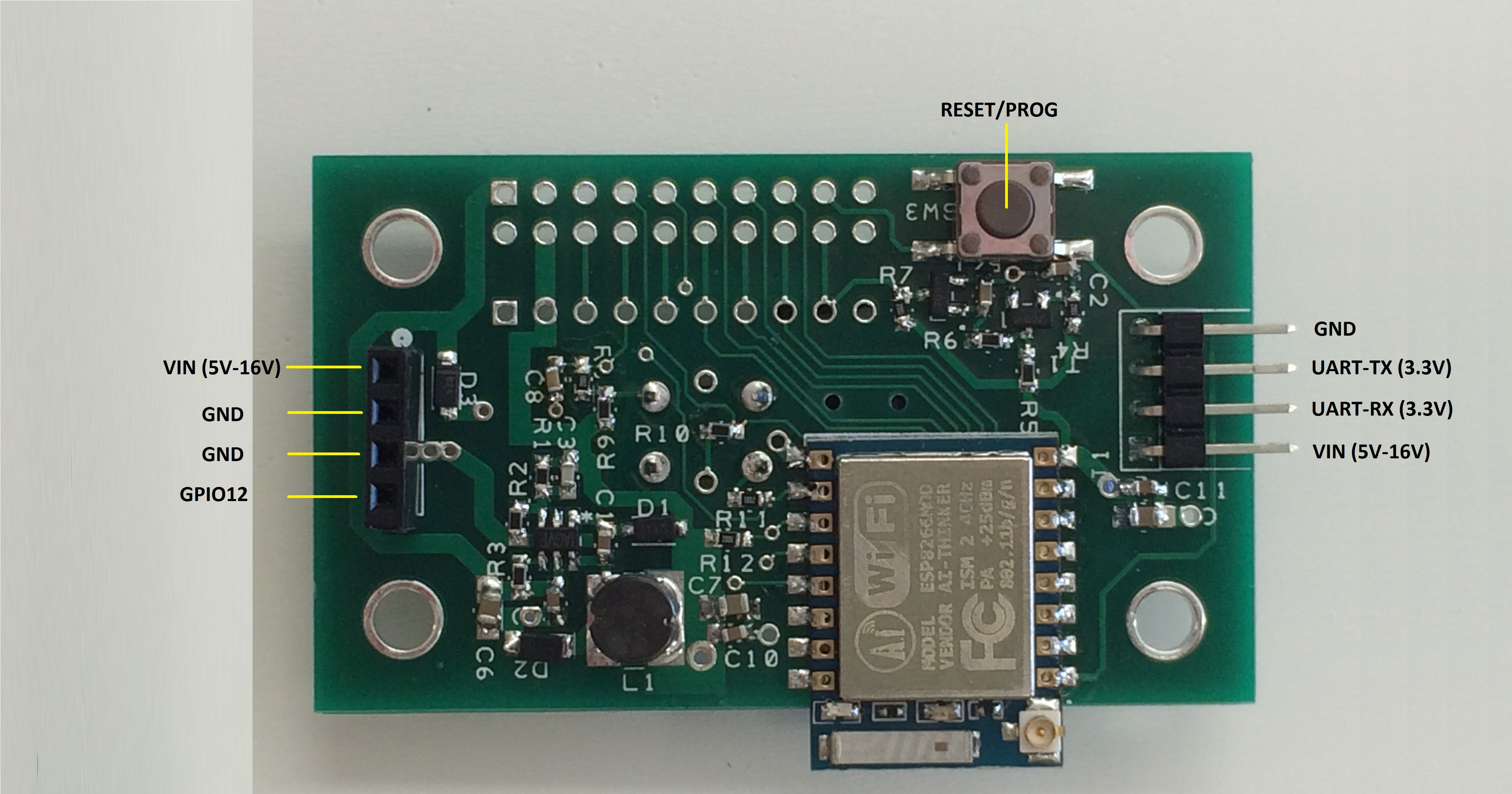
FlipFlop Switch Module Pinout
This is the pinout for the FlipFlop Switch Module P/N:100.00002.01.0
The Reset/Prog button is used to issue a module Reset or force the module to enter programming mode. Button press shorter than 2 seconds will issue a Reset. To enter programming mode hold the button for 2 seconds or more then release. The module will then enter programming mode. The module can then be programmed via the 4 pin serial UART connector as seen on the right side of the picture below.
- Flashloader Boot Messages
How to know if you are really in flashloader mode?
1- Connect to the UART @ 77400bps.
2- Then press the Reset for more than 2 seconds.
You should see something similar to this:
  ets Jan  8 2013,rst cause:2, boot mode:(1,6)
  or
  ets Jan  8 2013,rst cause:2, boot mode:(1,7)
For more details refer to the following: https://github.com/esp8266/esp8266-wiki/wiki/Boot-Process
- Normal Boot message
1- Connect to the UART @ 77400bps.
2- Then press the Reset for less than 2 seconds.
PowerUp Reset
ets Jan 8 2013,rst cause:2, boot mode:(3,0)
Hardware Reset
  ets Jan  8 2013,rst cause:2, boot mode:(3,6)
  or
  ets Jan  8 2013,rst cause:2, boot mode:(3,7)

- Expansion Connector There is a 20pin expansion connector. The Connector J3 has a pitch of 0.100mil. If you wish to use a breadboard, this is possible by using the first row of J3 and using the connector J4 providing you with a 0.300mil.
| J3 Pinout | Description | J3/J4 Pinout | Description |
|---|---|---|---|
| 1 | VIN (5V-16V) | 2 | GND |
| 3 | GND | 4 | 3.3V Out |
| 5 | GPIO2 | 6 | GPIO15 |
| 7 | GPIO5 | 8 | GPIO4 |
| 9 | UART-TX | 10 | UART-RX |
| 11 | CH_PD | 12 | ADC |
| 13 | GPIO14 | 14 | GPIO16 |
| 15 | GPIO13 | 16 | GPIO12 |
| 17 | RESET | 18 | GPIO0 |
| 19 | GND | 20 | GND |
