-
Notifications
You must be signed in to change notification settings - Fork 7
Final Integration
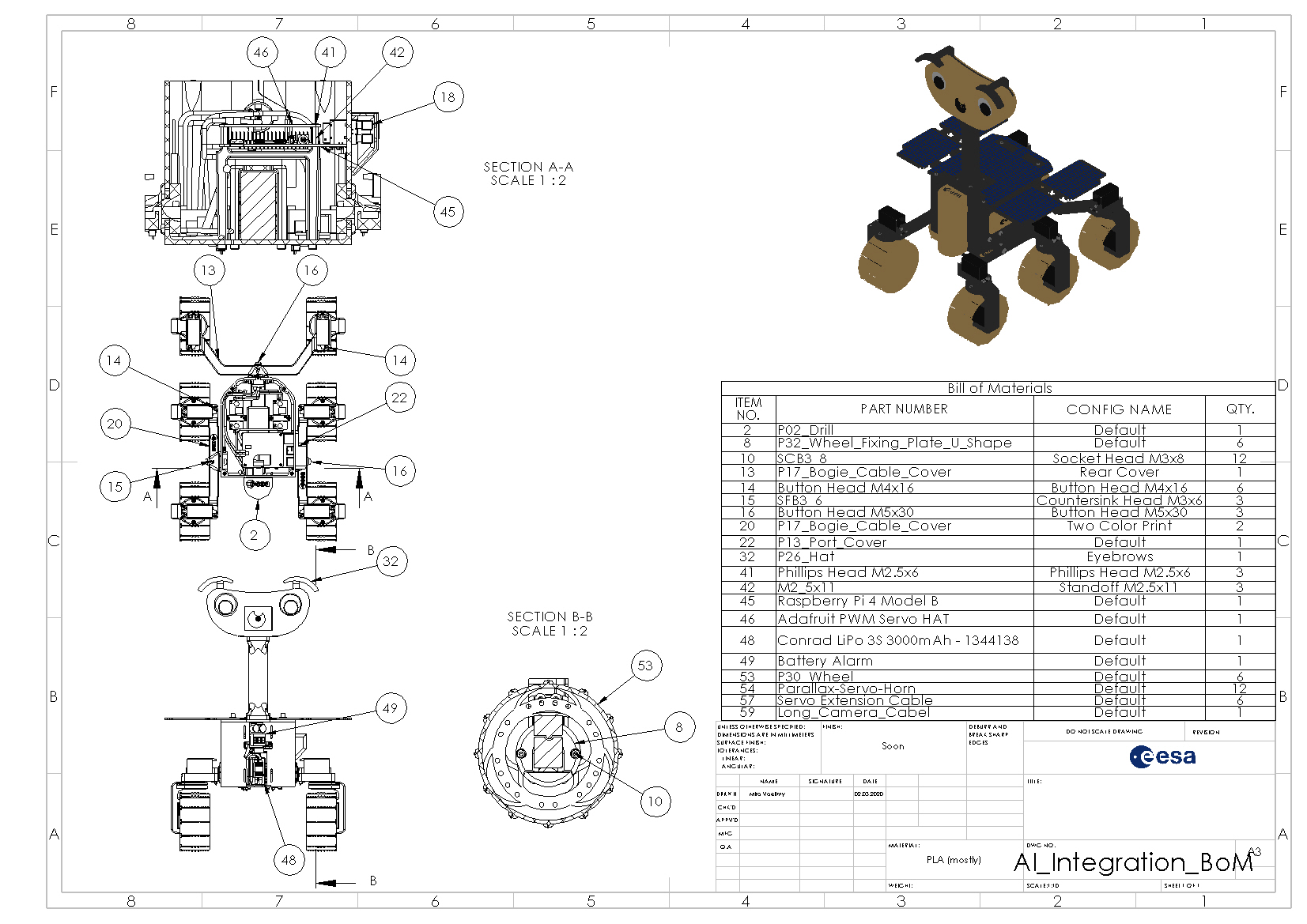
This is the final stage of the build and soon you will be able to drive ExoMy!
In the final integration, the bogies will be mated with the chassis, the electronic connected, the motors calibrated and finally the wheels installed.
A cardboard box (or the dedicated ExoMy maintenance stand (coming soon)) help with the installation of the bogies. The box should be a bit thinner then the body and high enough so the wheel brackets + wheels do not touch the table.
Watch the timelapse of our assembly by clicking on the image bellow to get an impression of the build.

The installation of the bogie is quite a bit easier if the chassis if done by two people together. It's also more fun! :)
The first step is to give ExoMy a pair of legs by installing the three bogies.
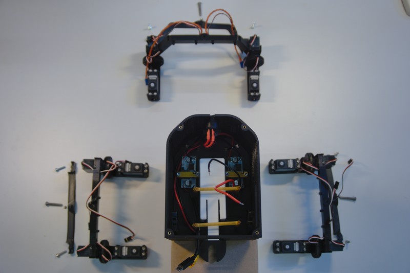
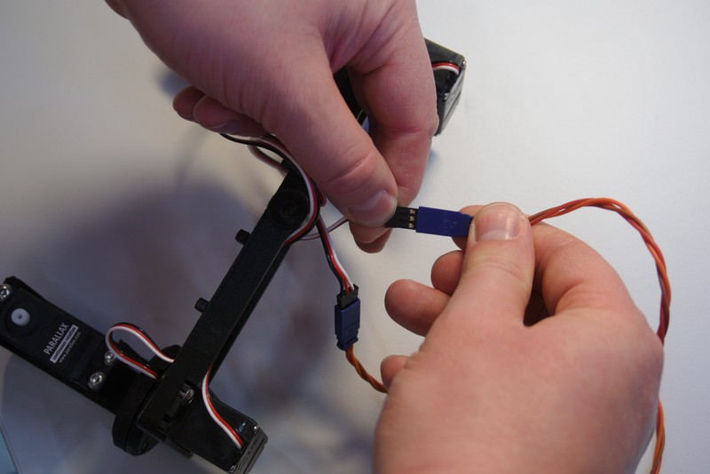
Connect the PWM extension cables to the rear steering motor and the side drive motors. The cables of the side steering motors should be long enough to reach inside the chassis to the PWM control board.
Install the M5x30 button head screw, around which the bogie pivots, into the bogie.

Only screw it until it slightly comes out on the other side.

Feed the cables through the bogie bearing channel. Feeding the extension connectors through the bearing might take a bit of patience.

Screw the pivot bolt into the bogie bearing. In order to set the play of the bogie bearing, tighten the bolt until you feel a lot of resistance in pivoting the bogie. Then loosen it until the bogie can be rotated easily again.

Make sure there are no visible air gaps between the bogie and the chassis or the bogie and the screw head.

The rear bogie assembled should look something like this.

With the cables routed into the body, it is time to hide them under the cable covers.
Begin with the rear cover and place it on top of the bogie. Make sure no cables are clamped in between the cover and the bogie.
Then screw the final M4x16 button head into the bogie to tighten it down. Be careful not to over-tighten these as the cable cover is purposefully not fully supported underneath. This makes the the cable cover bend down towards the center, which leads to a snug fit.

After you install the screws on the outside of the bogie, insert the center screw, again making sure not to clamp down on any cables.

Repeat this installation process for the other two side bogies.
With the side bogie cable covers, be careful when you mount them behind the center steering motors. Wiggle it around the cable but never force it.
The installation procedure is otherwise identical to the rear bogie cable covers.


Now insert the cables from all bogies into the cable guidance inside of the chassis.
Use Velcro or zip ties to bundle the four cables coming from each bogie together into a loom to finish of the bogie installation.

Use three M2.5x11 Male to Female standoffs to fix the Raspberry Pi into the chassis. Do not place a metallic stand off or screw in the corner next to the wifi antenna (corner next to GPIO pin 0). The metal from the standoff and screw will drastically reduce the performance of the wifi antenna. A plastic or nylon standoff and screw is fine however.
Note: On a model 3B the wifi antenna is a small, white, rectangular surface-mounted chip. On the 3B+ and 4B the antenna is a triangular shape cut into the PCB itself.
Route the cables from the left bogie between the chassis and the Pi before installing it.
Tighten the standoffs using 4 mm socket, wrench or your pliers. You can bend the holder legs to align them with the Pi mounting holes by reaching in through the battery hole in the front.

Connect the USB power cable to the Raspberry Pi. If your connector does not fit from the front, you might have installed the Raspberry Pi holder the wrong way around. In that case remove the Pi and install the holders the other way around.

Plug in the Raspberry Pi camera extension cable to the header. Make sure the contacts are facing the correct way as shown bellow.

With the cable plugged in, double check that the cable is seated properly. The contacts should align parallel to the connector. Then secure the cable in place by pressing down on the connector bracket.

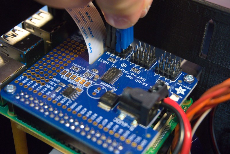
Then, feed the other end of the cable through the PWM expansion hat as shown.

Make sure no battery is installed before this step.
While it says +5V on the hat, it is no problem to operate the hat with the 6 V the DC/DC converters have been set to. Finally, connect the cables from the DC/DC converter to the + and GND screw terminals. Ensure the screws are done up tightly.

Align the PWM board to the Raspberry Pi and gently push it down with both hands.


Secure the PWM board using the three M2.5 screws. Verify that you omitted the standoff and screw in the bottom right corner.

Now connect the motor/servo PWM cables to the hat. It is very important you connect the cables the right way around. Black=GND, White=signal and Red=+V. Double check the corresponding colours on the PWM extension cables you are using. Compare this with the labeling on the PWM board and install the motor/servo PWM cables in any order. The order does not matter because motor/servo mapping will be set and dealt with in a software configuration step later on.
With all your cables installed, check again that all cables are connected correctly in respect the GND, +V and signal.
Check that both your power and motor switches are in the OFF positions.

Connect now the LIPO alarm to the battery. Make sure the red cable of the LIPO balancer plug is on the inside of the LIPO alarm as shown here.

Slide the battery in and connect the battery to the on board electronics. Do not switch ExoMy on yet!

Connect keyboard, mouse and a HDMI display to begin the calibration and configuration setup.

We have used wireless devices with USB dongles for this however it is fine to use conventional wired devices too.

Before starting ExoMy, go through the following checklist to eliminate potential error sources that might damage your hardware:
- Is the battery charged?
- Is the USB cable connected?
- Is the HDMI cable properly connected?
- Are the cables powering the PWM hat correctly plugged into +V and GND?
- Are ALL PWM cables plugged in the right way around?
If you can say yes to all these points it is finally time to turn on ExoMy! Activate first the power, then the motor switch and you should see your Raspberry Pi boot up on the screen.
Connecting the right motor to the right pin of the PWM board could be quite prone to errors, therefore a Python script will help you with determining the mapping.
The script goes from pin to pin asking you each time if and which motor moved. The config is saved in the config/exomy.yaml file. If the file does not exist, it is created based on the config/exomy.yaml.template file. The exomy.yaml file is set to be ignored by git, since it will be different for every ExoMy model.
In the software instructions you already learned how to run the Docker container for the motor configuration with:
sh ~/ExoMy_Software/docker/run_exomy.sh -cThe docker container will start in the Exomy_Software/scripts folder.
Run the config_motor_pins script with:
python3 config_motor_pins.pyFollow the instructions. Now, the motor configuration is known and the driving motors can be calibrated.
If you get an error message: bash: python3: command not found remove the 3 from python:
python config_motor_pins.pyThis applies to all following steps. Replace "python3" in the command by "python". This wiki describes multiple setups and software versions, so it is possible that in a older version, Python 2 instead of Python 3 is used.
The Parallax continuous rotation motor features a small potentiometer that allows the tuning of the stop position.
Flip your ExoMy over, so the motors/servos point upwards, to easier access the adjustment screws located at the bottom of the driving servo.

Check that you are still in the config Docker container, in the Exomy_Software/scripts folder from the previous step.
Now run the config_drive_motor_offset script with:
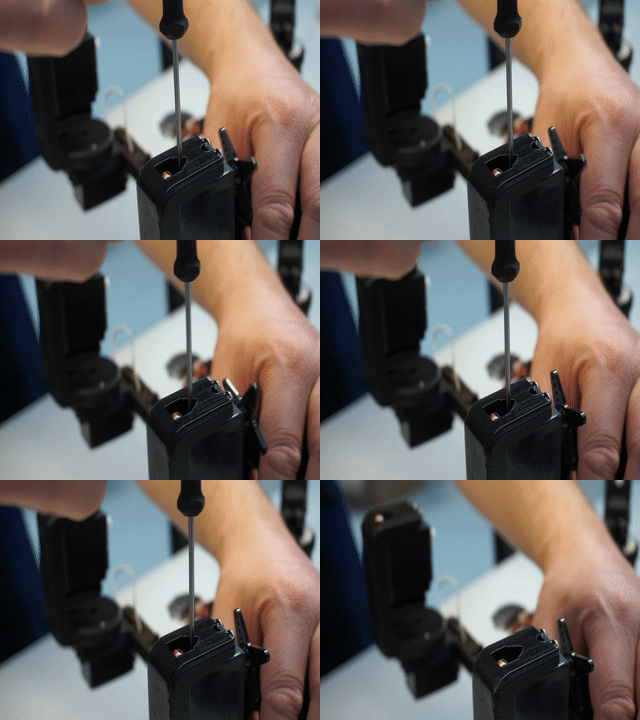
python3 config_drive_motor_neutral.pyThe script will send the PWM stop signal to the driving servos. (Which is not 0, see the script for more explanation) If the offset is not properly set yet, some motors might turn. Adjust the potentiometer of each motor with a screwdriver, until the motor does not move anymore in either direction. The movement is easier to see with a flange installed on the motor, like shown in the picture below.
Also the steering motors need a calibration for a proper zero position.
Check again, that you are still in the config Docker container, in the Exomy_Software/scripts folder from the previous step.
Now run the config_steer_motor_offset script with:
python3 config_steer_motor_neutral.pyThe script sets the motors to the intended neutral position and you can correct it with keyboard inputs. As a reminder, this is how the motors should be aligned at the end:

The "esa-prl:dev"-Branch contains an additional script to calibrate the maximum of the steering motors. This allows to configure the ExoMy for exact degree steering (better Ackermann and Point Turn).
Run the config_steer_motor_maxsteering script with:
python3 config_steer_motor_maxsteering.pyNow you can exit the Docker container with:
exitPower off the RaspberryPi and disconnect the monitor, keyboard and mouse for better handling.
With the motors configured and calibrated, it is now time to install the wheels.
Begin by removing the flanges from the driving motors. Keep the screws nearby.

Place the flange into the wheel

Insert the wheel fixing plate on top of the flange and secure it with two M3x8 socket head screws.

Do this for all six wheels.

With the rover still upside down, install the wheels to each driving motor. Pay attention not to over tighten the screw as the thread could be ripped out.


Cleanly shut down the Raspberry Pi by using the Terminal command sudo halt
Flip the rover on its wheels and pat yourself on the shoulder. You're almost done.
First, switch the rover off at with switches on the chassis. Connecting the camera while the Raspberry Pi is powered can destroy the camera.
Guide the camera cable through the neck and into the head. Now screw the top assembly onto the chassis using the four M3x8 socket head screws. The threaded inserts might squeak a bit, but that is no problem.

Now, connect the ribbon cable to the camera. The tin contacts should be facing the same direction as the camera aperture as shown bellow (blue tab on the back).

Next, slide the camera down onto the two hook screws and tighten them.

Add the port cover to the side by guiding it in from the top.


And install the drill to close off the body. You can keep the HDMI connected by routing it through the cutout on the bottom.

As a final step, insert a hat of your choice into the back of the head to finish the assembly of ExoMy!

Congrats!
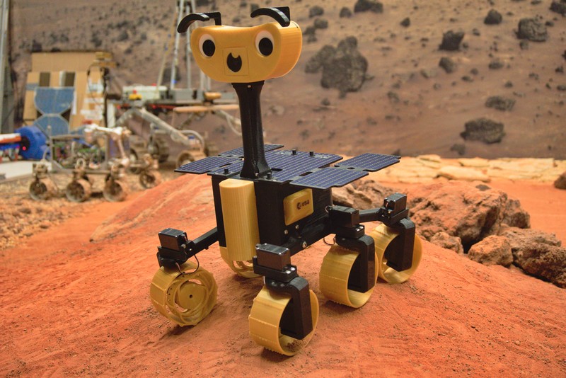
Head over to the Operation Instructions to learn how to drive ExoMy!
Build
- Getting Started
- Purchasing Instructions
- Software Instructions
- Manufacturing Instructions
- Assembly Instructions
- Optional Parts
Use
Contribute
Help

